Design Point Calculation
In the gas turbine design process, many alternative thermodynamic cycles are evaluated. Ultimately, a cycle will be selected which constitutes the cycle design point (cycle reference point) of the gas turbine.
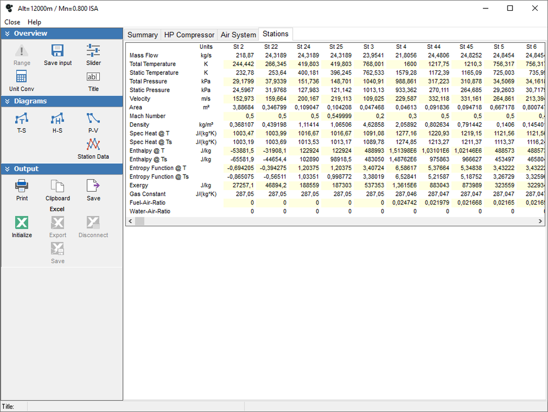
The mass flows, total pressures and total temperatures at the inlet and exit of all components of the engine will then be determined on the basis of this design point.
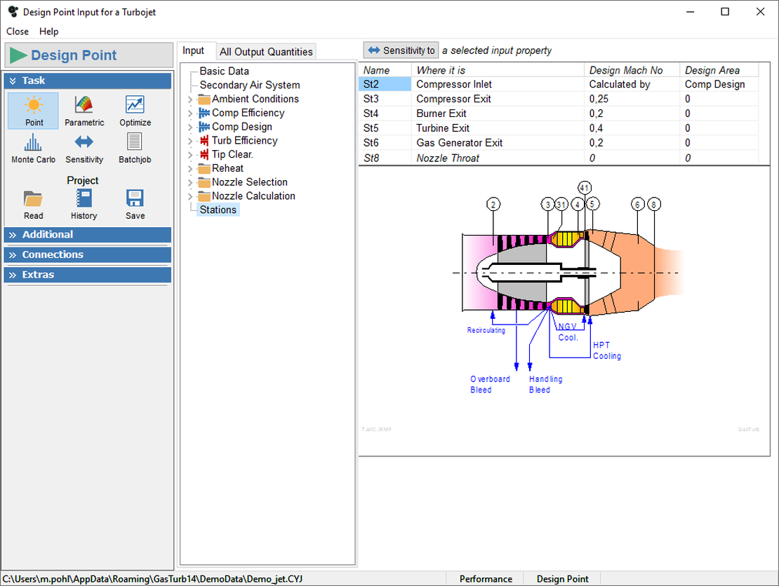
Selection of appropriate Mach numbers and hub-tip ratios at the component boundaries sets the aero-thermodynamically important dimensions of the gas turbine. Therefore by establishing a cycle design point, the geometry of the flow annulus may be defined and the weight of the gas turbine may be estimated.
Parametric Studies
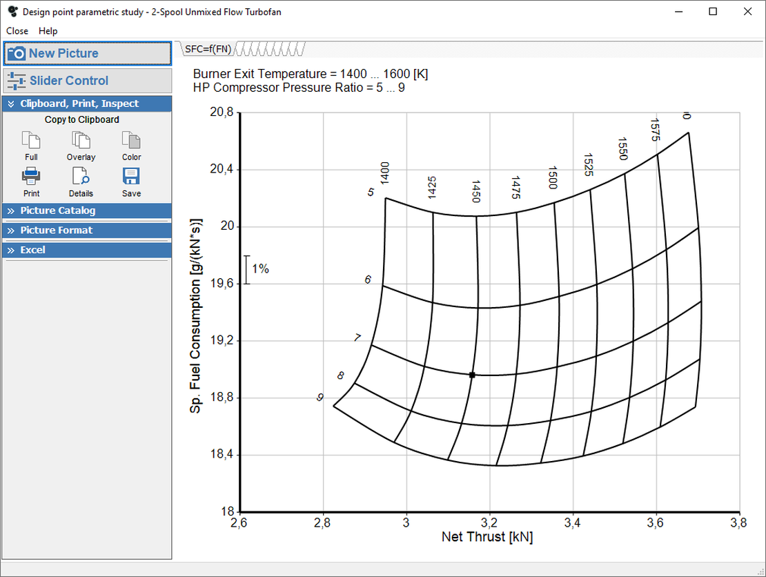
Parametric studies give an overview of the design space. Two parameters can be varied simultaneously generating a range of possible outcomes, visualized in a carpet plot. The calculation can be completed quickly and the results plotted in various formats.
The images may be printed or copied to the Windows clipboard, from where they can be pasted as vector graphics into PowerPoint or Word, for example.
Optimization
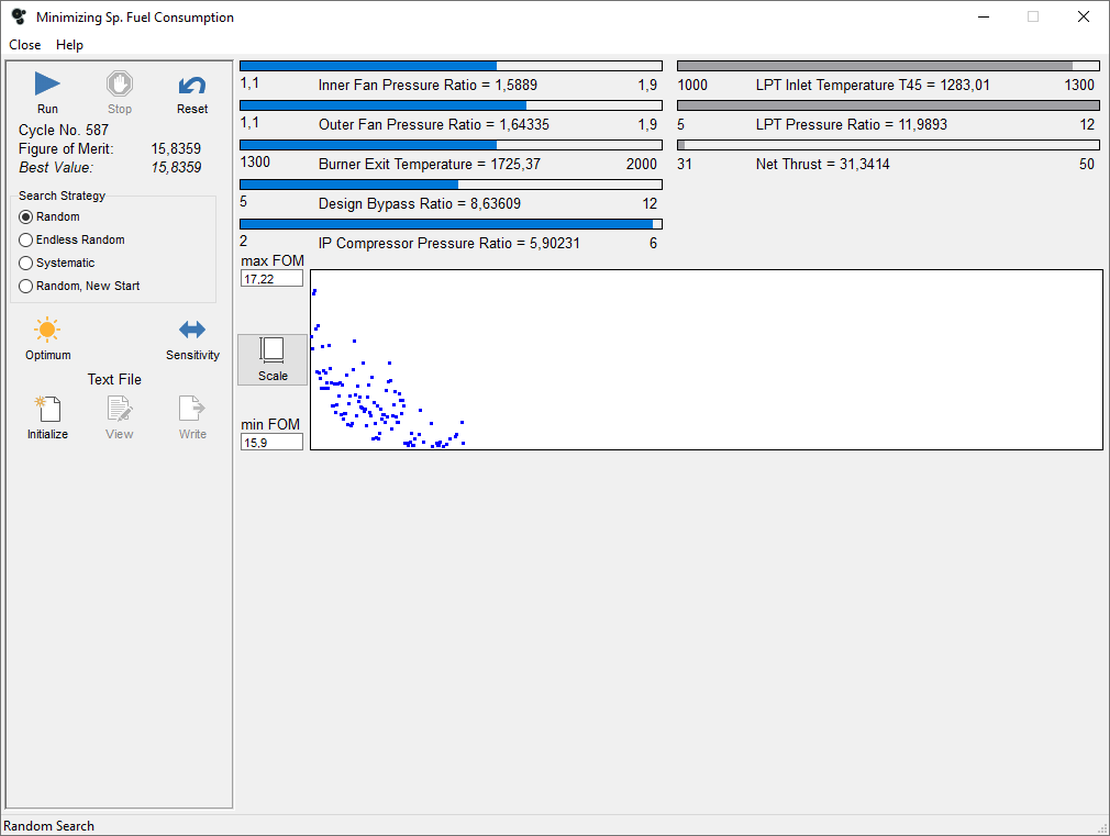
Numerical optimization can be employed for finding the best cycle. The optimization algorithm searches for the best solution taking into account up to 12 optimization variables and 12 constraints.
Any cycle output parameter, including the composed values, can be selected as a figure of merit that can be maximized on the one hand (e.g. specific thrust) or minimized on the other (e.g. specific fuel consumption).
The search strategy can either be random or systematic based on gradients.
Secondary Air System
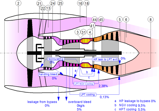
The secondary air system used in GasTurb is able to simulate internal flows used for turbine cooling and sealing as well as external flows for aircraft systems.
An engine diagram explains the secondary air system and the location of the thermodynamic stations, for which all the temperatures, pressures, velocities, etc. are shown in a table.
Thermodynamic Stations
GasTurb identifies the major thermodynamic stations between components using the nomenclature described in SAE AS755. The values at each station are summarized in a table.
